| Author | Message | ||
| davehouck
Moderator Username: davehouck Post Number: 1320 Registered: 5-2002 |
Here is Werner Witzel's (thebass) technical post on how pickups work. The original thread is here. Ok, so here�s the short story: 12dB/Oct roll off means that the output voltage of the Pickup drops by 12dB each Octave above the Pickups resonance frequency (the frequency where it has the highest output voltage). No clue ? Ok, here is the long story: A pickup (PU) mainly consists of the the magnets surrounded by a coil of mostly copper wire. Some PUs use silver wire because of the slightly reduced ohmic resistance of the wire, but that is very unlikely. This coil has an inductance (called L) which is measured in Henrys. But that�s only half the business because it neglects that the coil is non an ideal coil. The windings of the coil also have a capacitance (called C) which is measured in Farad. More likely you will see the capacitance value is expressed in micro (equals 10^-6) or nano (equals 10^-9) Farads because one Farad is a very huge capacitance. But it gets even more complicated. The resistance of the wire is not zero (unless it would be superconductive, which would require Alembics cooled down by liquid nitrogen and would make playing a bit uncomfortable). This resistance (called R) is measured in Ohms and is a series resistance to the inductance from above. If you consider all this you are able to substitute a PU with its equivalent circuit (only electrically of course) that looks like this:  Well we are almost there but again there is a bit more. A PU is not a quite unit, right ? If you hold the PU near a plucked string you can measure a signal voltage between it�s terminals. So there is also a signal voltage source which is in series to the coil wire (represented by the Inductance L and its Resistance R). Ok, let�s redraw the circuit diagram:  The signal from the strings is represented by the little circle with the wave inside and the PU is represented by its Inductance L, its Resistance R and the Capacity C between the windings. Ok, now that you now what is the equivalent circuit of the PU what can you do with it ? The signal from the strings in the above picture is considered as ideal which means that there is no distortion, no filtering or whatever. But this signal is only theorethically available because we need a PU (with given R, L and C) to get the signal from the strings. So if you now the values of R, L and C in the circuit above, you can calculate how the PU affects the sound from the strings. Ok, ok I know there is much more which forms the sound but lets concentrate on the electrical characteristics of the PU. Ok, so how does it sound ? Any Inductance L also has a Resistance (called XL) which is dependant on the frequency of the signal voltage. It doubles each octave, e.g. the Resistance at 200Hz is twice the Resistance at 100Hz. And again at 400Hz its twice as large as at 200Hz. To express this in a compressed form technicians express this with logarithmic values called decibel or "dB". A value of 6dB per Octave simply means that "something" (in this case the Resistance of L) gets doubled if the signal frequency gets doubled too. If you see something like "minus 6dB per Octave" this means that something is half of its original value if the frequency is doubled. The capacitance C behaves exactly the opposite as an Inductance: it divides its Resistance (called XC) by two each time the frequency gets doubled. Pooh, much math, eh ? Don�t give up, we are almost there. Look at the circuit diagram again: The Inductance L and the Capacitance C form a voltage divider from the signal voltage (coming from the strings) to the output terminals of the PU. As the signal frequency inreases, the Resistance value of L gets larger and larger and the resistance value of C becomes smaller and smaller. This results in a voltage divider which is dependant by the frequency of the signal voltage e.g. by the frequency of the strings. In this case it acts like a low pass filter. Because the inductance L causes the output voltage to decrease by 6dB/Oct (divided by two with each freqeuncy doubling) and the capacitance C does the same as well you can simply add both which results in ? Correct, 12dB/Oct. It still a lowpass but the signal decreases twice as fast as a simple lowpass. Since there are two frequency dependant components (L and C) this is called a second-order low pass with 12dB/Octave roll off. Since the resistance of L increases with the frequency and the resistance of C decreases with the frequncy there must be a very special frequency when the resistance values of L and C are equal. This frequency is called resonance frequency (called f0). At this frequency the PU has its highest signal voltage output, it can even be larger than the input voltage ! (To understand how this is possible you need to get into complex number mathemathics but then I will be killed by all board members.) At the moment it�s enough to know that above the resonance frequency the output voltage of the PU will decrease by 12dB/Oktave e.g. gets quartered by frequency doubling. The filter curve of the PU now looks like this: 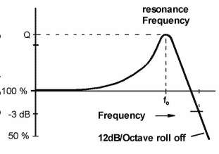 So what do you have now ? By knowing the values of L and C you are able to calculate how the PU affects your sound. You know at which resonance frequency you will get the highest output, which basically means the PU will "colour" the sound with a filter curve. The resonace frequency of normal PUs is in the range of several kilo Hertz which you can hear very good. The resonance frequency of low impedance Pus (like the Alembics) is very high, in the range of several ten kilo Hertz which is almost outside the audible range. The Alembic Q-Filter simulates the effect of the resonance frequency were Q is a value that determines the amplification rate at the resonance frequency. The higher Q the the higher the curve at the resonance and the more you can hear the filtering effect. When you now change the filter frequency by turning the Q-Filter you can simulate almost any filter curve of any PU on the market which is why the Alembic PUs and Q-Filter are so flexible and versatile. |