| Author | Message | ||
| smuprof
Intermediate Member Username: smuprof Post Number: 174 Registered: 12-2003 |
So I've been playing with a Line 6 X2 digital wireless rig and Shure wireless in-ear monitors for about 3 years. The X2 has a very flat, very clean 20 - 20k low impedance output (better than cables) and I like the freedom of wireless. (I know, I know - amps and cabinets and PA color the sound, negating flat, wideband transmission, but I believe in making as many components as colorless as possible). This worked great with my Mark King Signature 5 all this time, however with the new Series 2 bass, I'm back to either a DS-5 with a cable or playing on the internal batteries, which means suffering frequent replacement and no LEDs. My good friend Mr. Wayne McClemore pointed me toward building an external battery supply using the 5 pin connector, which solves multiple problems (easier to replace batteries, LEDs powered, longer battery life ( +/- 18v instead of 9v), etc.). I spent a lot of time thinking about how to do this in the most space efficient form - How to physically arrange the batteries, what boxes/containers were available, shielding, signal path, etc. The result is effectively a pocket DS-5 hardwired for mono operation. I finished the project this week and wanted to share the results with the forum. The construction only took about 12 hours, including making the case, but there was probably 40 hours of brain damage, online searching, shopping, etc. So if anyone else is interested in a solution like this, at least I can spare you the brain damage part. Even if you choose to use the internal batteries, this could be built as an emergency power back-up in case the batteries die mid-set. Just plug it in and go. One final note: This produces + and - 18v in the same connector that your treble and bass signal pass through. Not a problem when those fine folks at Alembic construct high quality DS-5s and cables, but you DO NOT want to be sloppy in your construction or wiring and DO NOT screw up the pin outs. After I finished, I checked pin-outs and voltages and polarities and resistance pin-to-pin side by side with my DS-5R at least a half dozen times, then said a prayer and plugged it into my S2. I'm very happy with the result, but I would discourage anyone from doing this unless you really know what you're doing. It's not that complicated, but there's a high price for mistakes. With that disclaimer and warning, here's the solution I came up with. | ||
| tbrannon
Senior Member Username: tbrannon Post Number: 1572 Registered: 11-2004 |
Looking forward to the reveal. You're building some suspense.... ;) | ||
| room037
Senior Member Username: room037 Post Number: 490 Registered: 9-2003 |
Hi, Our japanese club member has Powersuply for wireless system preowned by Mark King.(Please scroll down) I also made with master volume, mono-setreo SW and 2 phone jack. (It's little bit over spec for the size.) I wonder which is better for lifetime �}18V(series) or �}9V(parallel) on 4 batterys. I believe it's better for sound on 18V, but lifetime... Eiji | ||
| smuprof
Intermediate Member Username: smuprof Post Number: 175 Registered: 12-2003 |
Eiji - Very cool. Thanks for sharing. I looked at using a similar box, but wanted something that would allow me to quickly change the batteries. I thought about keeping it stereo, or making it switchable, but I knew I would never go to the trouble of using two wireless units and just wired it to combine the signals like the DS-5. when switched to mono. | ||
| smuprof
Intermediate Member Username: smuprof Post Number: 176 Registered: 12-2003 |
So the challenge for me was finding a compact enclosure that would allow easy access to the batteries, shielded, with enough room for the 1/4" jack, resistors, and power and signal wiring. I found a couple of plastic alternatives, thought about shielding paint, but ultimately decided on this: 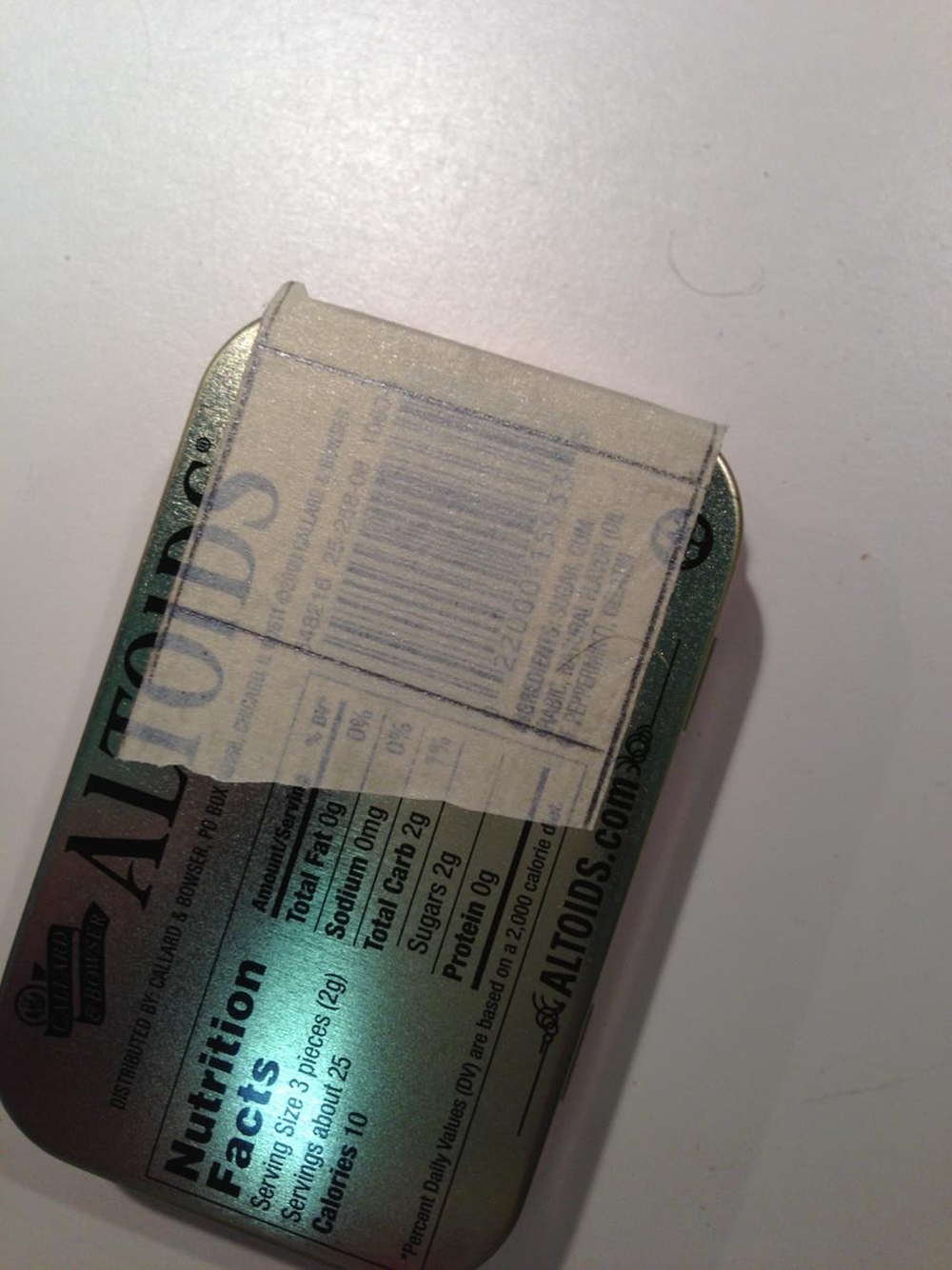 | ||
| smuprof
Intermediate Member Username: smuprof Post Number: 177 Registered: 12-2003 |
The enclosure is made of two Altoids tins glued back to back. Two 9v batteries will fit very neatly side by side, wide side against the back of the tin, leaving about 1/3rd of the top of the tin for the wiring and connections. The previous picture shows the back of the tin taped and ready to cut. I believe the "height" of the opening is about 1.25" from the top of the tin to the line closest to the middle of the tin. I marked the sides leaving just enough of a lip so I could glue it all around. | ||
| smuprof
Intermediate Member Username: smuprof Post Number: 178 Registered: 12-2003 |
Next step was to drill the four corners so I'd have a clean cut with no tearing on each side. 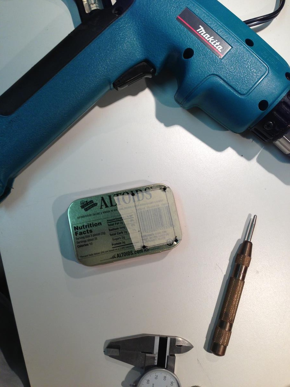 | ||
| smuprof
Intermediate Member Username: smuprof Post Number: 179 Registered: 12-2003 |
Next step was to cut the opening using a high speed rotary tool with a metal cutting disk. I cut this by hand and it came out fairly straight. The Altoids tins aren't very thick and the cuts were easy and quick. Here it is clamped down in the process of being cut: 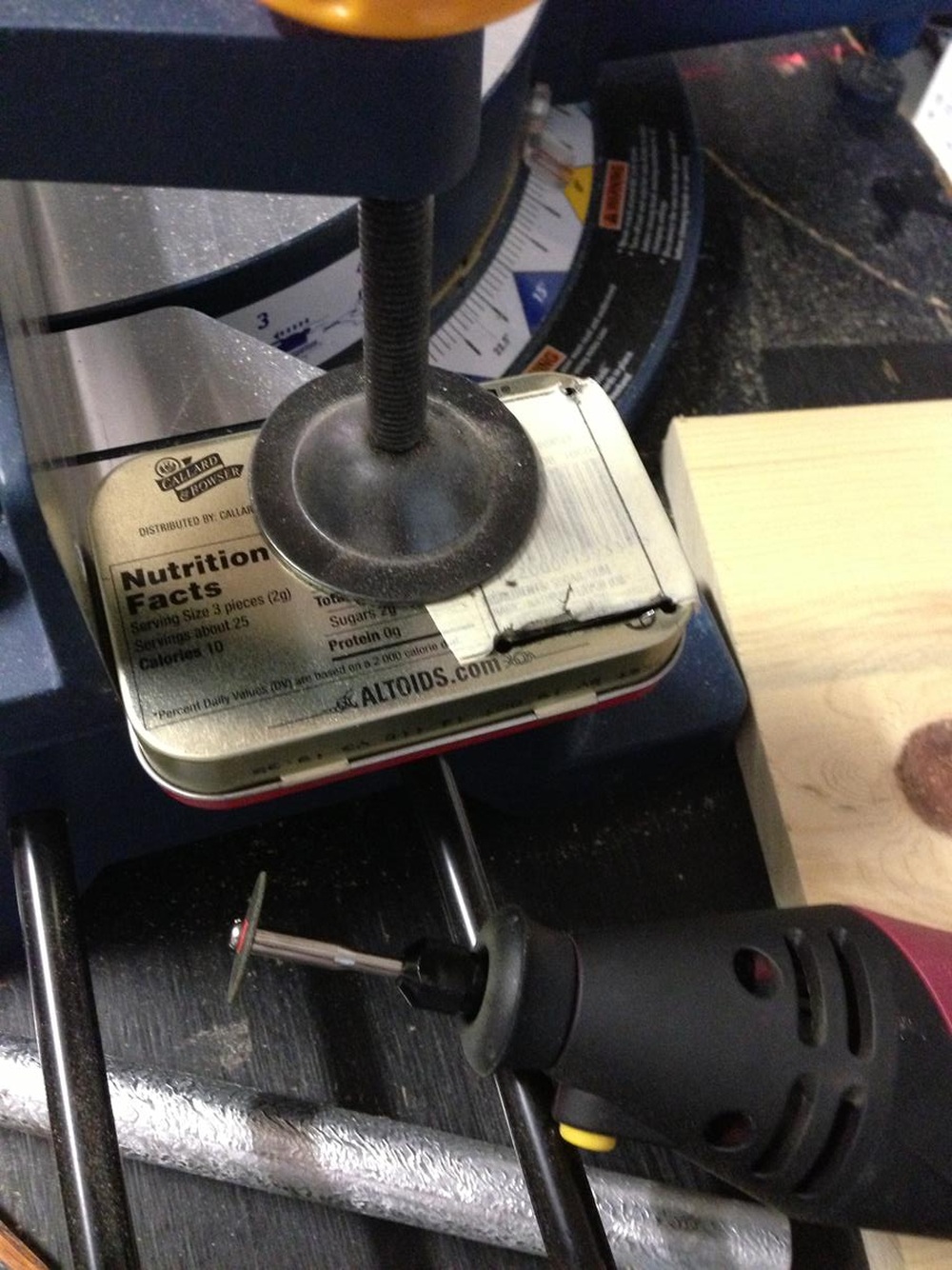 | ||
| smuprof
Intermediate Member Username: smuprof Post Number: 180 Registered: 12-2003 |
You only want to cut the top edge and the two sides. Leave the middle intact (it becomes the partition for the battery compartment and a shelf for the breadboard, as well as adds rigidity). Once complete, bend the "shelf" out of the tin. It helps to use a rigid strip of metal or wood and long-nose clamping pliers so the entire "shelf" bends along a straight line. Here's what it looks like bent out. This is the best opportunity to file and sand all of the edges so you leave nothing sharp to a) cut your fingers on and b) cut or short the internal wiring. More on that later. 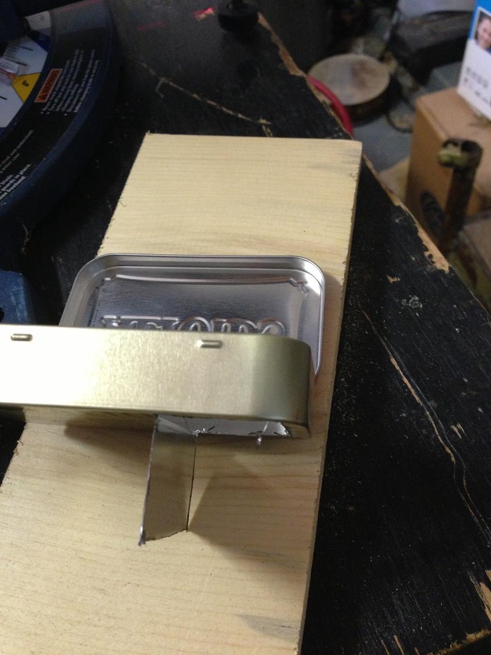 | ||
| smuprof
Intermediate Member Username: smuprof Post Number: 181 Registered: 12-2003 |
Once you've cleaned up the edges and filed things down smooth, use the same straight-edge technique with a pair of long-nose clamping pliers and bend the "shelf" in half, bending the outer edge up toward the opening. Fold it all of the way over, and then using regular pliers, crimp the folded edge tight so you now have a "shelf" that is half as wide, but twice as thick. Here's what it looks like:  | ||
| smuprof
Intermediate Member Username: smuprof Post Number: 182 Registered: 12-2003 |
Next step is to fold the "shelf" 180 degrees back into the enclosure space itself. This puts the folded edge facing upward (no sharp edges) and tucks the long side of the cut down into the back of the tin where it will be behind the batteries (again, no sharp edges you can reach). It also leaves a "channel" around each side of the shelf for battery wiring.  | ||
| smuprof
Intermediate Member Username: smuprof Post Number: 183 Registered: 12-2003 |
Now is a good time to test the fit of the batteries. I looked at a lot of different 9v battery connections - these are called safety connections because nothing can touch the terminals when they are attached. Maybe unnecessary, but they also make the mechanics a little more sturdy.  | ||
| smuprof
Intermediate Member Username: smuprof Post Number: 184 Registered: 12-2003 |
And here's what it looks like from the back . . .  | ||
| smuprof
Intermediate Member Username: smuprof Post Number: 185 Registered: 12-2003 |
Next step is to repeat the process with the second tin. I taped the second tin and traced the opening from the first to align the cuts and it worked really well. I elected to keep both hinges on one side, but it would work just as well if you had the hinges on opposite sides. Here the two tins are, unglued, testing the fit: 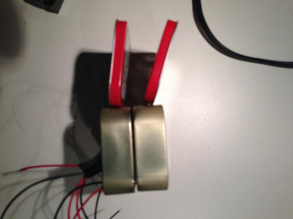 | ||
| smuprof
Intermediate Member Username: smuprof Post Number: 186 Registered: 12-2003 |
Here's another shot where you can see how the two shelves fitted together make a nice platform/compartment for the wiring and electronics, separated from the batteries. . . 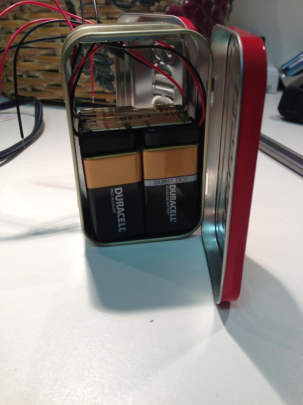 | ||
| smuprof
Intermediate Member Username: smuprof Post Number: 187 Registered: 12-2003 |
Next step (before you glue the tins together) is to create a flat surface for the 1/4" output jack. You probably could use a narrow jack and actually put it on one side of the interior "lip" or the other, but I wanted mine centered for aesthetic reasons, which required cutting the lip away on the top. This is a bit tricky as you want to cut close to the edge without cutting into the exposed outer surfaces. 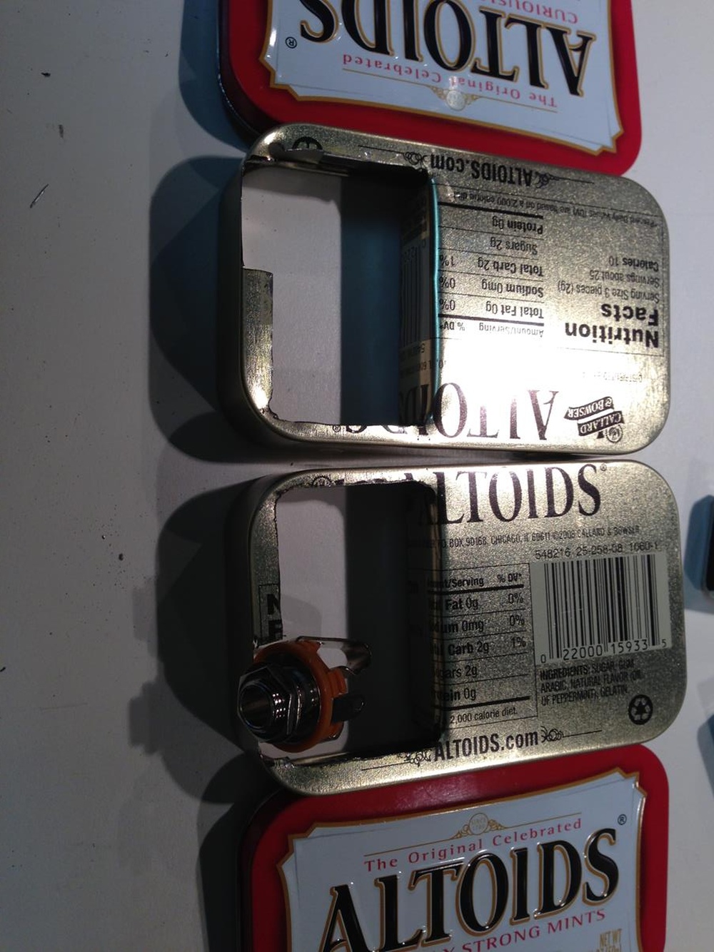 | ||
| smuprof
Intermediate Member Username: smuprof Post Number: 188 Registered: 12-2003 |
Checking to make sure I had enough flat surface to work with . . . 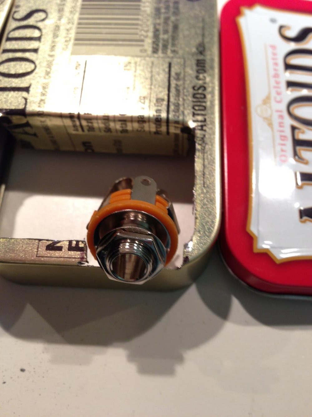 | ||
| smuprof
Intermediate Member Username: smuprof Post Number: 189 Registered: 12-2003 |
Checking to make sure I didn't cut too far into the outside walls . . . not perfect, but any gaps should be covered by the jack and washer.  | ||
| smuprof
Intermediate Member Username: smuprof Post Number: 190 Registered: 12-2003 |
Checking the alignment of the two cut-outs for the jack. Make sure you file down and clean up the edges.  | ||
| smuprof
Intermediate Member Username: smuprof Post Number: 191 Registered: 12-2003 |
Even with the filing, grinding and sanding, I was concerned about sharp edges and cutting myself or shorting the winding, so I put rubber edging around the interior lip. I'm sure there are commercial products out there, but I bought quarter-inch vacuum hose from the local auto parts store, slit it lengthwise, cut it to length and used super glue to tack it in place. Sturdy and much safer . . .  | ||
| smuprof
Intermediate Member Username: smuprof Post Number: 192 Registered: 12-2003 |
Sorry, skipped a step. Before I glued the rubber tubing in place, I glued the two tins together using super glue. Don't use too much, as you clamping two rigid, flat surfaces together. I used the plain old "thin" super glue, not the thicker gel that's available now. Once that's dried, you're ready to drill for the connections, starting with the 1/4" jack. | ||
| smuprof
Intermediate Member Username: smuprof Post Number: 193 Registered: 12-2003 |
Here's the result of drilling the hole for the 1/4" connector. Okay, since most of it is covered up with the washer, but probably the most difficult part of the project because you are drilling in the center of two thin metal surfaces that aren't attached (remember you cut away the flange inside). I used the rotary tool to start the hole, and a drill press to finish it, but it was still marginal in my opinion. In retrospect, you could actually offset the hole, even if it were close to the center, and probably get better results.  | ||
| smuprof
Intermediate Member Username: smuprof Post Number: 194 Registered: 12-2003 |
Here's the jack installed . . . 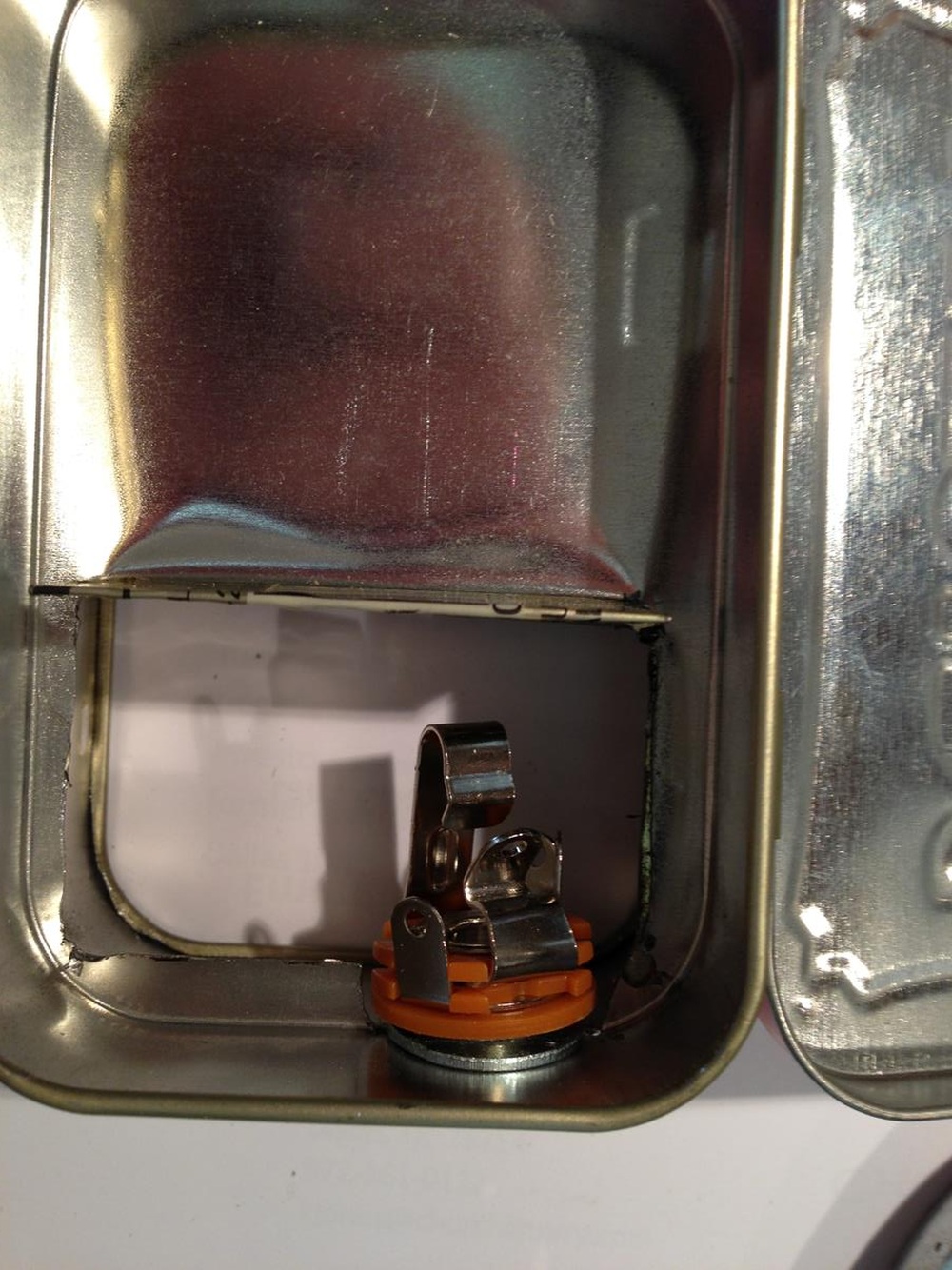 | ||
| smuprof
Intermediate Member Username: smuprof Post Number: 195 Registered: 12-2003 |
And what it looks like from the outside. Cleaned up pretty well. I added an extra washer on the inside to provide a broader, flat, sturdy surface to tighten the jack into. 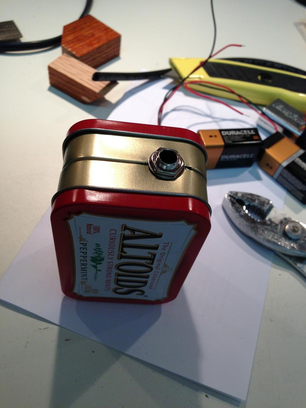 | ||
| smuprof
Intermediate Member Username: smuprof Post Number: 196 Registered: 12-2003 |
The next step was installing the 5 conductor cable. I used Canare mic cable, L-4E5C, which is the thin version of their star-quad cable - 4 conductors and excellent shielding. I used a rubber grommet to hold it in place and protect it from the metal edges. 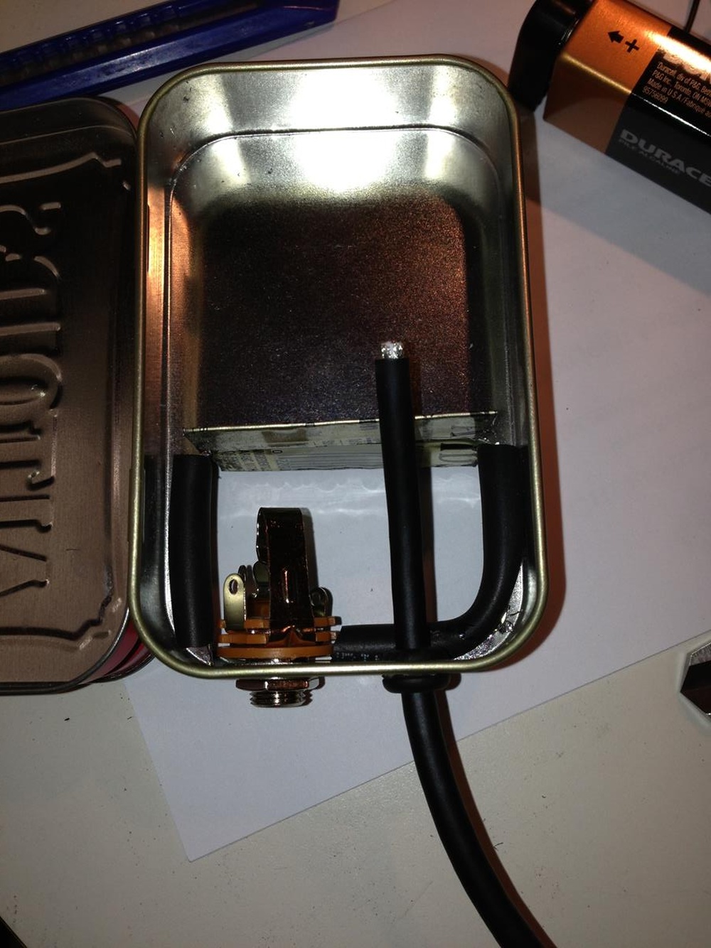 | ||
| smuprof
Intermediate Member Username: smuprof Post Number: 197 Registered: 12-2003 |
I used a small bread board to put the circuit together and provide a connection point for the power and signal cabling. Treble and bass signals go through a resistor combining network to produce a mono signal. Batteries are wired in series and tapped in the center to produce + 18v and - 18v to ground. I split the 5 conductor cable shielding 4 ways, discarded 2 of them, tied one to the power ground and the other to the ground/shield of the 1/4" connector. Since the box is metal, I figure this effectively grounds/shields the whole device. 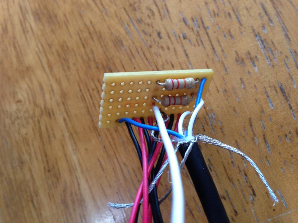 | ||
| smuprof
Intermediate Member Username: smuprof Post Number: 198 Registered: 12-2003 |
Here's the bottom of the breadboard. Power on the right side, signal on the left side. (Please, no commentary on my soldering skills - I don't do much anymore  ) )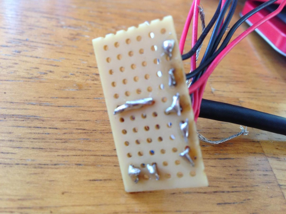 | ||
| smuprof
Intermediate Member Username: smuprof Post Number: 199 Registered: 12-2003 |
Here's the wiring completed and installed in the box. I cut another breadboard about the same size as the first one and used a hot glue gun to glue it to the bottom of the circuit board. Hot glue because you can disassemble it if needed, and it provides some stability and insulation between contacts. I then hot glued that assembly to the "shelf" we created when we bent the cut out into place. I put it beneath the 5 pin cable for spacing. I also cut and laid out the breadboard so it would fit neatly on the shelf. 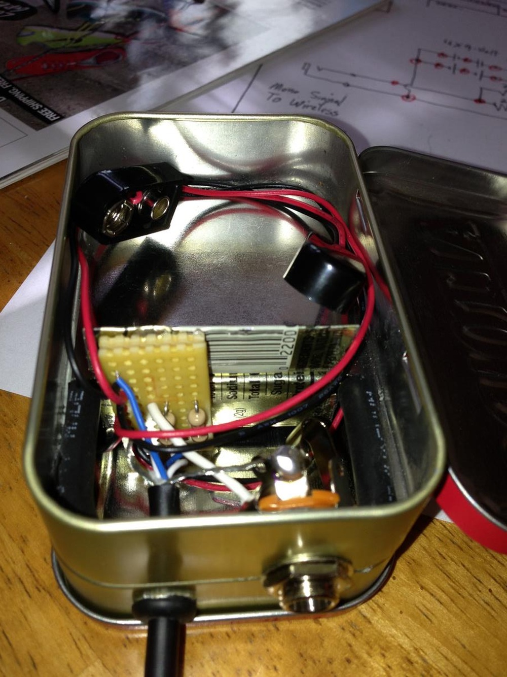 | ||
| smuprof
Intermediate Member Username: smuprof Post Number: 200 Registered: 12-2003 |
Here's everything with the batteries installed. I used narrow weather-stripping foam at the base of the box to keep the batteries snug against the "shelf." I also put two strips on the inside of each lid to hold them snug when the box is closed up. 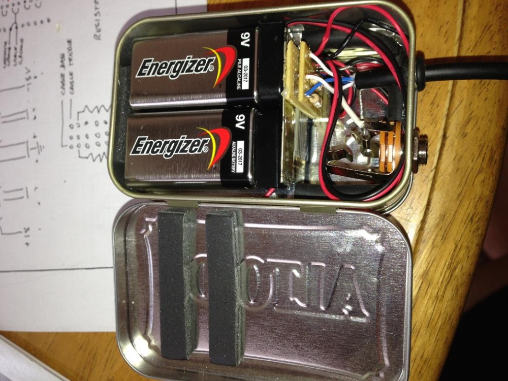 | ||
| smuprof
Advanced Member Username: smuprof Post Number: 201 Registered: 12-2003 |
Here's the finished box, all closed up. I used a Neutrik NC5FRX-B 5 pin right angle XLR connector. I tried to find the connectors that Alembic uses with the flat backs just for consistency, but couldn't and found at least one indication that they're no longer available. The one I used is fine (it has a round back), but let me share one caution: it comes disassembled, with parts of the shell and the pin insert, which clicks into place with a retaining spring when you insert it into the shell. Do all of your soldering on the pin insert BEFORE you click it into place in the shell . . . because it ain't coming out once you do Don't ask me how I know this . . . 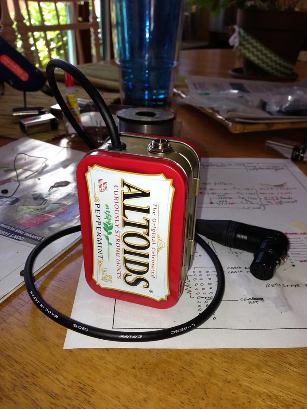 | ||
| smuprof
Advanced Member Username: smuprof Post Number: 202 Registered: 12-2003 |
And here it is plugged into the S2. I originally was going to glue a belt clip on it, but I figured out it would fit (very snugly) into the Neotech wireless pouch that attaches to my strap. So I now just have two of the pouches, one for the wireless transmitter and the other for my Altoids battery supply. 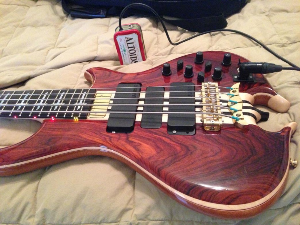 | ||
| smuprof
Advanced Member Username: smuprof Post Number: 203 Registered: 12-2003 |
Couple of final notes: 1) My apologies for misspellings and missing words - my laptop keyboard will skip multiple characters sometimes - I tried to catch and correct them, but probably missed a few. 2) I'll keep you posted on battery life under real world conditions. I'll probably switch over to Lithium-Ion rechargeables. I've had great luck with the HiTech brand - they have a higher current rating and seem to work for a good 8 hours in my transmitter and wireless in-ear rigs. I'll try those in the Altoids box as well. Hope everyone has a safe and happy 4th of July! | ||
| room037
Senior Member Username: room037 Post Number: 491 Registered: 9-2003 |
This is my power supply.(Sorry for out of focus) Parts and batteries are mounted intensively. 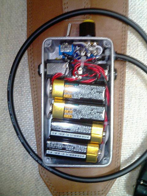 | ||
| wylie_j
Junior Username: wylie_j Post Number: 15 Registered: 8-2005 |
Smuprof good on ya Mate! I can hardly make out what u have built but i just want to say "More Power to U" for being so adventurous with such a fine 5-string Alembic bass i'm jealous u got the serious deluxe model.....joking! so this looks to be a home made wireless system? if it works well maybe u should "pitch" it to Alembic....coz they don't have one of these! | ||
| jazzyvee
Senior Member Username: jazzyvee Post Number: 3521 Registered: 6-2002 |
Excellent. I wonder if alembic have any desires to make similar device. Jazzyvee | ||
| smuprof
Advanced Member Username: smuprof Post Number: 204 Registered: 12-2003 |
Eiji - I like your power supply, and I believe your description is most appropriate: the wiring and components are intense Very clever. I'm curious about the 2 jacks: separate Treble and Bass like a DS-5, or something else? | ||
| smuprof
Advanced Member Username: smuprof Post Number: 205 Registered: 12-2003 |
Wylie - thank you for your kind words. The box provides portable external battery power for the electronics and LEDs, so you can be completely wireless. The 1/4" output goes to the wireless transmitter in a pouch on my strap. Jazzy - thanks, I would love it if there were an Alembic version. The big issue is the package sizing. I have a shoe box of discarded ideas for this. I was going down the same road as Eiji, which obviously works well, but even after looking at dozens of different size boxes, they all seemed a little small or too large. The other challenge was a container that allowed for quick, easy access to the batteries for replacement. I'm not sure if Eiji's box is assembled with the 4 screws. I was looking at miniature hinges and magnets in a box like that to create easy access to the batteries, but ultimately decided I couldn't do it cleanly and I didn't want to have to disassemble the box to replace the batteries. For a manufacturer like Alembic, they could have a vendor produce exactly what they wanted in volume, including cavities for the batteries. Shure's wireless unit does a great job using spring tabs behind a cut-out that doesn't allow you to insert the battery incorrectly. When you snap the battery door shut, it holds the battery firmly in place. Something like that would be ideal. I definitely think there's a need/market for something like this. | ||
| smuprof
Advanced Member Username: smuprof Post Number: 206 Registered: 12-2003 |
One more thought I've been toying with: R/C hobbyists use heavy duty lithium ion rechargeable cells that are essentially 3.7v. Hard to get to 9v with that, but five cells in series would give you 18.5v, and ten would allow you to have plus and minus 18v with extreme life in a compact package. I'm not a hobbyist, but I have learned you need a specialty charger for these sorts of cells that monitors the charge and balances the current on each of the cells. Something for another day, but it would be great to have a compact box you could drop in a charger that would go for hours and hours. | ||
| room037
Senior Member Username: room037 Post Number: 492 Registered: 9-2003 |
Yes, my box has 2 output just like DS-5. I thought it for stereo or double mono by 2 wireless systems. But these are "over spec" that i said. If i will make next one, it will be simple. Eiji | ||
| charles_holmes
Advanced Member Username: charles_holmes Post Number: 265 Registered: 3-2009 |
All of this is way over my head and I feel as though I'm not worthy to own an Alembic now. Oh Well.. that's what I get for only wanting to be proficient at bass (which is marginal @ best!)I should have paid attention in electronics class! Nice bass there J.T. | ||
| smuprof
Advanced Member Username: smuprof Post Number: 207 Registered: 12-2003 |
Charles - Ha! I'm pretty sure you're worthy and I'm pretty sure my band mates would have preferred I spent the time practicing instead of building the box. But the heart wants what the heart wants. Now that it's done, guess it's back to the woodshed for me . . . | ||
| terryc
Senior Member Username: terryc Post Number: 2116 Registered: 11-2004 |
Along with my own made wood backplates for my MK this is a great example of making a square peg fitting a round hole..brilliant!!! | ||
| hankster
Advanced Member Username: hankster Post Number: 325 Registered: 6-2004 |
"Curiously strong", indeed! Nice project! R. | ||
| smuprof
Advanced Member Username: smuprof Post Number: 210 Registered: 12-2003 |
So I promised a battery life update, and I want to share a nice feature of this particular setup. Here's what the rig looks like, wireless plus battery pack, on my strap. Nicely hidden from the audience. Adds a little weight, but once you commit to ebony and coco bolo, what's a little more? 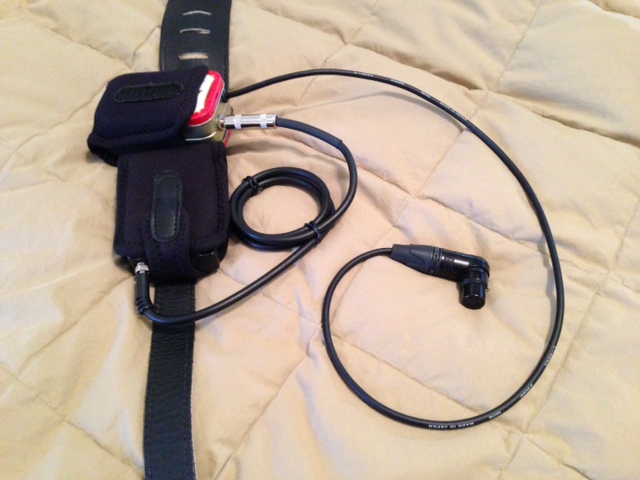 | ||
| smuprof
Advanced Member Username: smuprof Post Number: 211 Registered: 12-2003 |
Pouches are Neotech wireless pouches (medium - they make a small and medium, not really a large). Here's the rig with the wireless transmitter out. Battery pack feeds the 5 pin XLR on the body, as well as feeds the signal back to the box. From the box, the signal goes to the X2 transmitter pack. 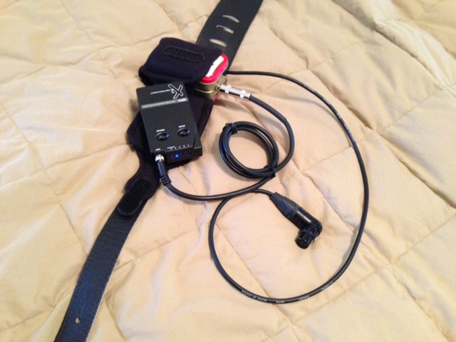 | ||
| smuprof
Advanced Member Username: smuprof Post Number: 212 Registered: 12-2003 |
And here it is strapped on. I can easily reach behind me and access the transmitter to turn it on and off. 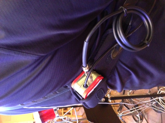 | ||
| smuprof
Advanced Member Username: smuprof Post Number: 213 Registered: 12-2003 |
The battery life with 4 new alkaline batteries is a solid 12 hours, powering LEDs and electronics. I ran them all the way down to the point they stopped working (no LEDs, no sound). They worked great right up until they stopped working. No distortion, no loss, just dead. The box was designed to make it easy to replace the batteries - pull it out of the holster, open both sides, pop out the 9v's and put in 4 new ones. Probably less than 60 seconds. Here's the cool part: I play in church and so they died halfway through the service. I didn't realize they were dead until I strapped on to play the special, so not enough time to replace the batteries. No problem. Pulled the 1/4" jack from the battery pack and plugged it directly into the bass. Now the internal batteries are powering the electronics (no LEDs, but better than no bass for the special). Worked great and carried me through the service. Essentially, the internal batteries become the emergency back up for the external battery pack. No more worrying about battery failure. | ||
| smuprof
Advanced Member Username: smuprof Post Number: 214 Registered: 12-2003 |
One final thought: I've switched pretty much exclusively to lithium polymer and lithium ion 9v rechargeables. I consistently get the same 12 hour life (or more) as the 9v alkalines, only with the benefit of being able to recharge every couple of shows and knowing you're starting every event with plenty of battery power to get through the show. This battery life is pretty consistent in the battery pack, transmitter pack or wireless in-ear monitor pack. Plus the benefit of not buying and trashing alkalines every week or so. I like the HiTech brand (higher current capabilities). I recently bought some rated even higher from China, but have not had the chance to test them. We've pretty much switched the entire band. Here's the charging station I made: 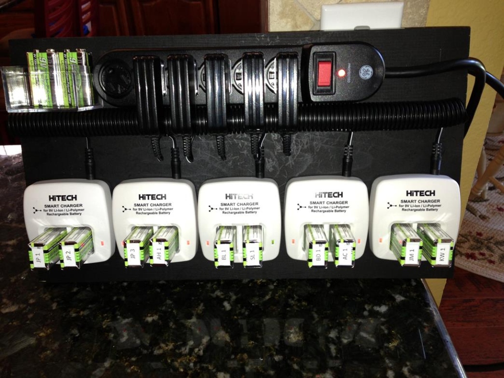 |