| Author | Message | ||
| charles_holmes
Advanced Member Username: charles_holmes Post Number: 392 Registered: 3-2009 |
Hi everyone! I would like to build a 5 pin cable. I found where to order the Neutrik female 5 pin right angle connector and Male 5 pin. Now I am not sure what type of cable to order( I looked on my cable from Alembic and it reads Belden 1192A) but when I tried to order it, it was nowhere to be found. Can someone out there please tell me where to order the cable I need ?...And what the cable is called. Lastly, does anyone have photos on connecting the Neutriks up to the cables? Thanks all!! I'd like to build a 60' 5 pin cable!!!! | ||
| keith_h
Senior Member Username: keith_h Post Number: 2175 Registered: 2-2005 |
Charles, What you are looking for is Star-Quad microphone cable. I like Canare L-4E6S. It has a braided shield like the Belden 1192A but is more flexible. You can find both by the foot at Markertek. For wiring I just ensure that the same wire goes to the same terminal on both ends and that the shield goes to pin 1 and the ground lug. For reference: Pin 2 is the neck pickup signal Pin 3 bridge pickup signal Pin 4 is +V (+15V to +20V) Pin 5 in -V (-15V to -20V) Keith | ||
| stephenr
Member Username: stephenr Post Number: 53 Registered: 9-2014 |
My suggestion would be Mogami cable. Mogami makes high end cables for recording studios and also sells their wire in bulk. They make some real nice instrument cables, too. Pretty sure you need to get balanced microphone cable. Good chance others will chime in with more suggestions/info. Good luck! | ||
| terryc
Senior Member Username: terryc Post Number: 2338 Registered: 11-2004 |
60'!! What you planning on doing, watching the band at the back of the room off stage whilst you play along? | ||
| charles_holmes
Advanced Member Username: charles_holmes Post Number: 393 Registered: 3-2009 |
Yep Terry!!!I'm going to be incognito! The mystery bassist! | ||
| slawie
Senior Member Username: slawie Post Number: 742 Registered: 8-2002 |
You should be aware of a phenomenon called volt drop. The voltage supplied at the other end of a 60' cable would be Somewhat attenuated. The cable manufacturer should be able to provide data or try this; http://www.calculator.net/voltage-drop-calculator.html At 60' you should be OK slawie | ||
| rustyg61
Senior Member Username: rustyg61 Post Number: 1578 Registered: 2-2011 |
Chalie, I took Keith's advice when I was building my spare cable for my Europa & went with the Canare L-4E6S. I got mine from New York Pro Audio on Ebay for $11/10'. I bought 20', so it was $22 & came as one full 20' length of cable. Here is the link - http://www.ebay.com/itm/CANARE-L-4E6S-STAR-QUAD-BALANCED-MICROPHONE-CABLE-BULK-UNTERMINATED-10-BLUE-/130625922467?ssPageName=ADME:L  C:US:3160 C:US:3160 The Canare is much more flexible than the standard cable. I roll mine up into a 4" coil to fit inside my case with no problem. My situation was the opposite of yours though, I wanted a shorter cable than the one the bass came with. I'm rarely more than 10' from my amp at the small venues we play, so I wanted a shorter cable. The Canare comes in colors too, so of course I had to get blue to match my Blue Orca! Here are the Neutrik connectors I used - http://www.markertek.com/product/nc5mx-b/neutrik-nc5mx-b-5-pin-xlr-m-cable-plug-w-black-shell-gold-contacts http://www.markertek.com/product/nc5frx-b/neutrik-nc5frx-b-5-pin-right-angle-xlr-f-black-shell-gold-contacts Here's the wiring diagram, the Canare is a 4 conductor cable with a shield, so you use the shield as the ground - 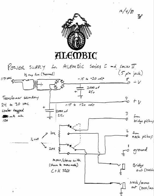 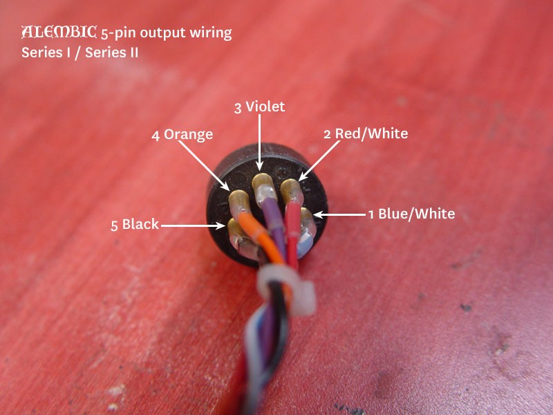 Here's the finished cable in use -  (Message edited by rustyg61 on March 22, 2015) | ||
| rustyg61
Senior Member Username: rustyg61 Post Number: 1579 Registered: 2-2011 |
Not sure why my links aren't active on my post, but you can copy & paste them into a new browser page & they work. Maybe one of the moderators can activate my links.... | ||
| mica
Moderator Username: mica Post Number: 8469 Registered: 6-2000 |
We make 100' cables for Stanley Clarke - so 60' should be no problem. We prefer the Belden 8424 but it's difficult to get in the boot of the connector. We're using it now. I've also like the Gotham Audio Star Quad cable, but it's a little delicate for the way most people (and techs) handle it. | ||
| edwin
Senior Member Username: edwin Post Number: 1950 Registered: 5-2002 |
Hey, my cable is blue, too! I think it's Mogami. All of the above are good brands. I've been looking for a good option to combine in ears and the 5 pin in one cable. Maybe two channel Star Quad snake cable.... | ||
| edwin
Senior Member Username: edwin Post Number: 1951 Registered: 5-2002 |
The Belden 8424 looks like a great option. Nice fat wires at 20 ga. Most star quad is 1/2 24 gauge at best. I might get some for my next build. | ||
| keith_h
Senior Member Username: keith_h Post Number: 2177 Registered: 2-2005 |
The Canare uses 21 AWG wire which is another reason I like it. Keith | ||
| edwin
Senior Member Username: edwin Post Number: 1953 Registered: 5-2002 |
Not exactly. The specs at the Canare website have the following clarification: Cond-AWG (Qty./mil) Cross Sec. Area mil.� **Quad AWG AC - #24 40/3.15 310 #21 **Effective AWG of combined twin conductors. I know the layout here is confusing, but the website says: http://www.canare.com/ProductItemDisplay.aspx?productItemID=53 So far the Belden is the clear winner when it comes to wire gauge. | ||
| keith_h
Senior Member Username: keith_h Post Number: 2178 Registered: 2-2005 |
Oops. Haven't looked at the mechanical specs for a long time and just stopped at the 21 AWG in the summary. Won't argue on the 8424. It isn't cheap though. Keith | ||
| charles_holmes
Advanced Member Username: charles_holmes Post Number: 394 Registered: 3-2009 |
Thanks guys! I'm torn between building it myself or having the mothership hook it up. Mica, how much would Alembic charge to do this? Here's my email bajarone123@comcast.net Thank you! | ||
| mica
Moderator Username: mica Post Number: 8474 Registered: 6-2000 |
Email is on the way to ya! | ||
| charles_holmes
Advanced Member Username: charles_holmes Post Number: 398 Registered: 3-2009 |
Just received the 60' red cable and Neutrik connectors, but man how do you tell which white wire from the other white and blue from the blue when trying to solder?!! | ||
| elwoodblue
Senior Member Username: elwoodblue Post Number: 1577 Registered: 6-2002 |
Continuity tester. (got a battery and little light bulb?) | ||
| charles_holmes
Advanced Member Username: charles_holmes Post Number: 399 Registered: 3-2009 |
Ah!!Simple..yet effective..sniff..sniff..I love you man!...Yet one more question (after this statement) obviously I do not have an electrician's skill, but I'm not afraid to try basic stuff and I do not know what some things are called so...looking at the color photo of the 5pin wiring, what are those little clips called that connect to the pins? I need to purchase some. Thanks!! | ||
| charles_holmes
Advanced Member Username: charles_holmes Post Number: 400 Registered: 3-2009 |
Rusty, Ok..I'm stumped I didn't study basic wiring I was too busy playing my guitar and bass. So..in laymen's terms (with 1st grade drawings) how do I hook up the 4 wires to the 5 plugs? Stumpo da bassman | ||
| keith_h
Senior Member Username: keith_h Post Number: 2185 Registered: 2-2005 |
Those aren't little clips. The wires are soldered into the cup. What you see in the picture looks to be heat shrink tubing used to reinforce the wire and insulate the connectors. The same thing could be done with plastic tubing. I don't bother with any of it as the connections don't get stressed due to the strain relief built into the connector housing. Keith | ||
| edwin
Senior Member Username: edwin Post Number: 1973 Registered: 5-2002 |
What Keith said. Using heat shrink to reinforce the connections is great, but I never do it, most people don't. Maybe I should, but I treat my cables pretty well. It's just like Alembic to do it absolutely perfectly. Make very sure that you have each pin going to its corresponding pin (1 to 1, 2 to 2, etc.). It doesn't much matter which wire you use for which pin, although pin 1 should be the shield, as long as you are consistent. You don't want to mix up the power supply voltage with the signal. On one connector, the pins go 1-5 left to right and it's the opposite on the other. I love the smell of solder in the morning, it smells like.... | ||
| rustyg61
Senior Member Username: rustyg61 Post Number: 1600 Registered: 2-2011 |
Chalie, what Edwin said is exactly what I did. Pin 1 for the shield then get a continuity tester or as I did, an ohm meter & make sure you have the same wire to the corresponding pin on the other end. You may need a magnifying glass to read the PIN numbers on the socket, but they are labeled. Once you get it built double & triple check the you have continuity from pin 1 to pin 1 on the other end, & pin 2 to pin 2, ect. Also check between each pin & the others to make sure there is not continuity. It is very easy for a stray strand of glob of solder to short out the adjacent pin & that would be a bad thing! It's tedious work, but not too complicated. Just take your time & check your work. You have to get the sockets pretty hot for the solder to bond to them. It should look like it is painted onto the lug, not laying on top of it where you can see a crack between the solder & the lug. If you don't get the lug hot enough the solder will bead up on top of it & not make a good bond. Good luck! | ||
| edwin
Senior Member Username: edwin Post Number: 1975 Registered: 5-2002 |
I don't know if I'm telling you something you don't already know, but the easiest and best way to solder something like this is to tin the connections first. That means strip the wire and melt solder onto it, then melt solder into the cups in the connector. Then, when you solder them together, just put them together and heat both until the solder flows freely between them. Keep them very still until the solder hardens. Putting them together and then trying to apply the solder at the same time guarantees and inferior connection. Tinning and connecting as above also ensures that you don't have too much extra solder swimming around and reduces the chance for solder bridges as Rusty warns about. Go slow and have fun! It's very empowering to make your own cables and I haven't had a failure that wasn't due to direct abuse in decades. I can't say the same for commercial cabling. | ||
| jazzyvee
Senior Member Username: jazzyvee Post Number: 4452 Registered: 6-2002 |
This may be an obvious question but I've not read it explicitly stated, so just wanted it categorically stated. If the pins were somehow wired wrongly so that power was applied to the bass in wrong places would the electronics fry or are there some sacrificial components in the bass/DS-5 to prevent serious damage to either? I would imagine a fuse would protect the DS-5. But would the bass electronics survive? | ||
| terryc
Senior Member Username: terryc Post Number: 2349 Registered: 11-2004 |
I gather the IC chips blow first but putting 110/240V through anything designed for 18V is bound to cause terminal destruction | ||
| keith_h
Senior Member Username: keith_h Post Number: 2186 Registered: 2-2005 |
The fuse is strictly for the AC voltage side of the DS5. Without a schematic of the Series electronics I cannot say conclusively of there would be damage if the +/- 18VDC were miswired. I can say there is a definite risk of damage so it pays to be careful when making you own cable. I use an ohm meter to check any cable I make for correct wiring and to ensure there are no shorts between terminals. As has been mentioned above a simple continuity tester can be used to accomplish the same thing. Keith | ||
| charles_holmes
Senior Member Username: charles_holmes Post Number: 401 Registered: 3-2009 |
Hello all, I just wanted to tahnk all of you for your invaluable information. Since I didn't have the tools to perform the soldering, I had my buddy Kenny Wittman hook me up! The 60' of cable is working exceptionally well!!!!!!!!!!!!! | ||
| rustyg61
Senior Member Username: rustyg61 Post Number: 1635 Registered: 2-2011 |
Chalie, glad you got your cable built & it's working good! I love a happy ending! |