| Author | Message | ||
| mica
Moderator Username: mica Post Number: 3405 Registered: 6-2000 |
Here's what James came up with to get a complete set of Anniversary electronics with 4 additional switches mounted in a Dragon Wing body shape: 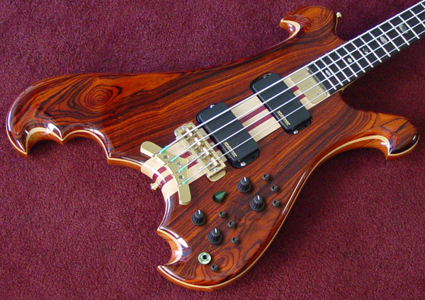  Sadly, there is no way to do this with a side-mounted jack. This mock-up is not an exact layout. Once you approve the arrangement, I'll make a drilling template that you can view if you like. | ||
| rickkessler
Junior Username: rickkessler Post Number: 20 Registered: 1-2006 |
Mica, Thanks for the mock-up of the electronics. I agree that it would be better to have the side mount jack. Would it be possible to have a recessed strat-type jack in on the rear of the bass almost exactly behind where the output jack is pictured? If not, then I'm fine with the front output jack where you show it and would love to see the drilling template. Also, I know Valentino confirmed this when he spoke to my wife, I just want to make sure we're now proceeding with this as a 32" scale bass. Is this (electronics layout approval) the first step in the process or has anything else been done yet? Is there any way to see some choices for the top? Thanks so much for everyone's attention to this project. --Rick | ||
| keith_h
Senior Member Username: keith_h Post Number: 494 Registered: 2-2005 |
Rick, This looks interesting. I'm curious to see how it progresses. I would like to make one comment on the controls. If you use a right angle 1/4" plug, the stereo/mono switch location could be a problem. On my BB the LED switch is below the jack and prevents me from using 90 degree plugs since they toggle the switch when the chord moves. Keith | ||
| rickkessler
Junior Username: rickkessler Post Number: 21 Registered: 1-2006 |
Keith, Thanks for the input. It's a good point, although I generally don't use 90 degree plugs. I think I'm stuck with the jack in front, but for me, having that electronics layout is one of the most important reasons I went to Alembic for my bass. I'll let you know what happens. Hopefully, Mica will post the drilling template soon. | ||
| rickkessler
Junior Username: rickkessler Post Number: 22 Registered: 1-2006 |
Mica (and Val), I just realized that it was silly to consider a rear recessed jack since it would have to be where the electronics cover plate goes. I'm fine with the front-mounted jack, so please go ahead with a drilling template. It would be great if you can post it when it's ready. Also, I'm still wondering about the questions I posed earlier regarding the 32" scale and the ability to see some choices for the cocobolo top. Thanks again for everything. --Rick Posted on Monday, July 10, 2006 - 1:32 pm: -------------------------------------------------------------------------------- Mica, Thanks for the mock-up of the electronics. I agree that it would be better to have the side mount jack. Would it be possible to have a recessed strat-type jack in on the rear of the bass almost exactly behind where the output jack is pictured? If not, then I'm fine with the front output jack where you show it and would love to see the drilling template. Also, I know Valentino confirmed this when he spoke to my wife, I just want to make sure we're now proceeding with this as a 32" scale bass. Is this (electronics layout approval) the first step in the process or has anything else been done yet? Is there any way to see some choices for the top? Thanks so much for everyone's attention to this project. --Rick | ||
| valvil
Moderator Username: valvil Post Number: 925 Registered: 7-2002 |
Hello Rick, yes, I confirm that it will be a medium scale 32 inch. This is the first step in the process, so now we can go ahead with the drilling template. We have cut a few more pieces of coco bolo; Mica will post some pictures next week. Are there any instruments that you can point us to that feature a coco bolo piece that is to your liking? That will help. Valentino | ||
| rickkessler
Junior Username: rickkessler Post Number: 23 Registered: 1-2006 |
Thanks for the response Val. I assume, you still have the nut/12th fret measurements, too? Let me know if I need to resend them. In terms of the cocobolo, I like the bass pictured above. But I like the wood in the two attached photos even more, particularly the dragonwing. I guess I like a more red color tones and lots of very defined circles and wavey lines, i.e. "busy" is good. Can't wait to see some picutures. Thanks again --Rick. 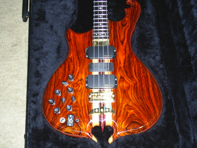 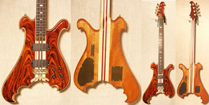 (Message edited by rickkessler on July 14, 2006) | ||
| georgie_boy
Member Username: georgie_boy Post Number: 61 Registered: 8-2005 |
sorry jacko, but this top is maybe even more beautiful than yours IMO ! Absolutely speechless!!!!!!! Grain -wise, I think coco bolo is just__________ G | ||
| rickkessler
Junior Username: rickkessler Post Number: 24 Registered: 1-2006 |
Val, Mica: Just checking in to see if there were any new developments. Hope all is well with you and the folks at Alembic. --Rick | ||
| valvil
Moderator Username: valvil Post Number: 932 Registered: 7-2002 |
Hello Rick, I saw your body about to be glued up today, and the the new neck has also been made. I don't know if Mica has had a chance to take pictures, but it's looking really good. Personally, I think it's an even nicer piece of coco bolo than the first one. Mica will be on holiday next week, so pictures may have to wait until she gets back. Valentino | ||
| mica
Moderator Username: mica Post Number: 3455 Registered: 6-2000 |
I did take a picture today while I was out in the shop. Check your build record in a few minutes for an update. After talking to James and Chip, the drilling template will be made after the cavity is routed. Then we can make any small adjustments needed. I'll show you the template before we drill the holes, but it won't be for a little while. | ||
| rickkessler
Junior Username: rickkessler Post Number: 26 Registered: 1-2006 |
Mica, Valentino: Thanks for the picture. I agree wholeheartedly with Valentino that it is even nicer than the original and I couldn't have hoped for better. Thank you for making the effort to fulfill my request and exceeding my expectations. In terms of the electronics, I'm fine waiting to see the template. Also, before the neck gets too far, I just wanted to remind you that, in addition to the width specifications and thin profile, we had also discussed rounding off the upper edges of the fretboard sides so that it has a broken-in feel, something that Reverand does with their Rumblefish basses. Thanks for listening and for all you have been doing!!! --Rick | ||
| mica
Moderator Username: mica Post Number: 3474 Registered: 6-2000 |
Mock up for the drilling: 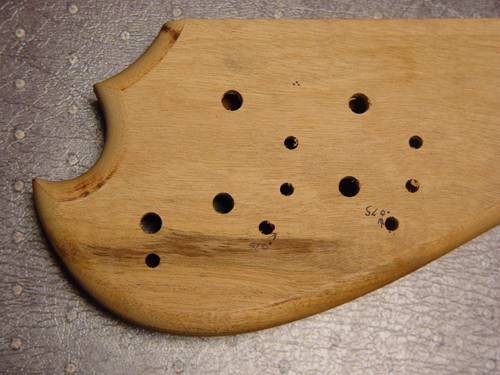 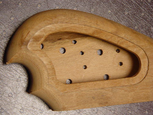 Moved 2 of the switches slightly, plenty of room to clear the edge of the cavity. In the back shot you can see how the area is slightly hollowed out, where the controls are placed outside of the plate. | ||
| rickkessler
Junior Username: rickkessler Post Number: 27 Registered: 1-2006 |
Mica, Thanks for posting the pictures. I've been away on vacation and hadn't been able to get on the web, so I'm just now seeing this. I don't know how far this has progressed since you posted the pictures, but I did have 2 questions: 1. I don't see a hole for the pickup selector. It was located between the two volume switches in the orignal mockup. There seems to be a marking in this picture at about that point, but not sure if that's why it's there. 2. Is it possible/make sense to move the "stereo mono switch" hole from where it currently is --at about 6 o'clock relative to the jack hole in the first picture -- to 3 or 4 o'clock so that there's no danger of the cable hitting it? Having built basses before, I understand that the wiring/switch sizes may not make that practical from a construction standpoint, but wanted to ask. Other than those 2 issues/questions, I think it looks fine. Thanks again for the post. | ||
| mica
Moderator Username: mica Post Number: 3557 Registered: 6-2000 |
1. Yeah - that mark is where the hole is now! Apparently I whisked it away from the bench before it was done. 2. No prob. Here's the revised layout just to make certain that I understand your instructions: 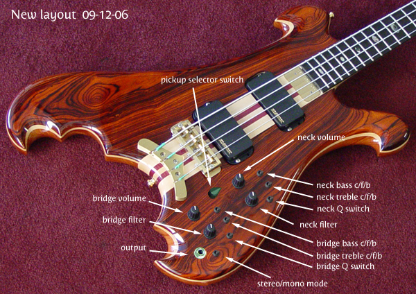 | ||
| rickkessler
Junior Username: rickkessler Post Number: 28 Registered: 1-2006 |
That's it. Thanks Mica. |