| Author | Message | ||
| precarius
Intermediate Member Username: precarius Post Number: 124 Registered: 11-2005 |
Hey-I recently bought a 1976 Series 1 that I can't get to work with the DS5 power supply. I sent the DS5 to Alembic and they said there is no problem with it and also 2 different XLR cables check OK with a multi-tester, which I guess narrows it down to the bass? Apparently, in its past, the bass has had the wiring modified since I get both the neck and bridge pickups through the 1/4 inch jack using a standard mono guitar cable. Here is a picture of the control cavity. Any thoughts or suggestions? Thanks. Mike 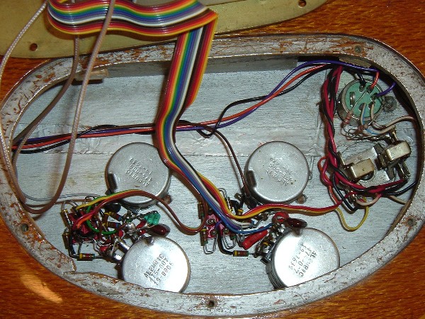 | ||
| precarius
Intermediate Member Username: precarius Post Number: 125 Registered: 11-2005 |
Here is just the output jacks. 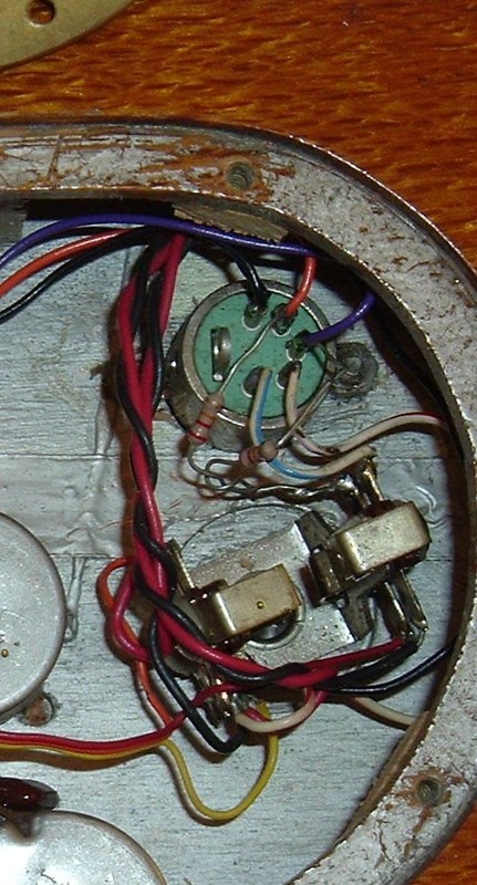 | ||
| davehouck
Moderator Username: davehouck Post Number: 4834 Registered: 5-2002 |
Just to clarify; In all positions of the pickup selector switch you're getting no output through the five pin connector. And in all three pickup positions of the selector switch you are getting the appropriate signals through the 1/4" connector. And you tried two different 5-pin cables with the bass. Just glancing at the picture. If you haven't already, with your multimeter check that current is moving through those solder joints on the 1/4". | ||
| precarius
Intermediate Member Username: precarius Post Number: 126 Registered: 11-2005 |
"In all positions of the pickup selector switch you're getting no output through the five pin connector." That is correct. I get a noise when I move either of the volume controls, but it is just noise. "And in all three pickup positions of the selector switch you are getting the appropriate signals through the 1/4" connector." That is also correct. One position is standby, one position is bridge pickup only, one position is both neck and bridge pickups, and one position is neck pickup only. And yes, I tried two different 5-pin cables. Are there certain solder joints on the 1/4" that you are concerned about? It's like a bank of kudzu in there. Thanks. Mike | ||
| davehouck
Moderator Username: davehouck Post Number: 4839 Registered: 5-2002 |
I'm not an electronics guy. You mentioned that the 1/4" had been rewired from stereo to mono, so I thought that would be a good place to start. A cold solder joint might be preventing signal from going from the 1/4" to the 5-pin. | ||
| dela217
Senior Member Username: dela217 Post Number: 772 Registered: 6-2002 |
It is kind of hard to tell from the picture, but it looks like the mono conversion was done correctly. The purple and violet wires that are coming from the pickup selector switch were originally wired to the 1/4 inch jack. Then from there were jumped over to the 5 pin. In the mono conversion, they are attached to the 1/4 inch jack, but together using the resistors. In the stereo setup, the violet and orange wires are run to different terminals on the 1/4 inch, not just to one side. Make sense? I have a schematic of the conversion, but do not have a scanner so I can't post it. But, I am looking at the schematic and I cracked open my series II, and it looks ok from here. BUT I would definately put some heat shrink tubing or electrical tape on those resistor leads. They could possibly ground out causing all sorts of woes. I am sure someone at Alembic can post a scan of the schematic here for you. It looks as though your output problem could probably be a simple one. If I were you, I would convert it back to stereo and just use the power supply. I personally find that I RARELY use the 1/4 inch output. I only use it for headphones or tuning. But that's just me. Series basses really can go through the 9 volts quickly. That is a pretty piece of lacewood by the way! Congrats on the new bass. Michael | ||
| davehouck
Moderator Username: davehouck Post Number: 4840 Registered: 5-2002 |
This post might be helpful. | ||
| precarius
Intermediate Member Username: precarius Post Number: 127 Registered: 11-2005 |
Thanks Dave and Michael. | ||
| precarius
Intermediate Member Username: precarius Post Number: 136 Registered: 11-2005 |
In looking at the post Dave linked to, I don't exactly understand what this means. "grounding flag wiring same for stereo or mono: yellow ribbon cable black to pin 1 XLR black to harness red to battery 1 black to battery 2 (order is not critical)" Can someone explain this to the simple-minded, electronically challenged, me? Thanks. | ||
| davehouck
Moderator Username: davehouck Post Number: 4925 Registered: 5-2002 |
I'm not an electronics person either but, Looking at the top picture in the pdf referenced in the above link, My guess is that the "grounding flag" is the metal strip at the top of the picture. And the five wires in the passage you quoted are the five wires attached to the metal strip. So my guess is that you would want to find the same five wires going to ground on your 1/4" jack. | ||
| dfung60
Advanced Member Username: dfung60 Post Number: 240 Registered: 5-2002 |
Here's something to check. In your second photo, there's a short red/white striped wire that starts at pin 4 of the XLR (this pin is the 4th one counting clockwise from the black wire). On the 1/4" output end it should be connected to one terminal of the jack with no other wires. It's hard to tell in the photo, but it looks like it's soldered together with a yellow and black wire, but this may just be the camera angle. This is important! The 1/4" jack is much more complicated on a Series bass than any other instrument that I know of. In addition to the regular tip/ring/sleeve outputs for stereo outputs and signal ground, it's also got two switches that are flipped when you insert the plug. One of those switches turns the battery on when you insert the plug; the other switch effectively cuts off the external 20v power to the onboard electronics. External power on the XLR5 connector are the two striped wires on pins 4 & 5. It looks to me like the red/white stripe wire from pin 5 is connected to ground rather than the 1/4" jack switch (this is the "normally closed" or "n.c" connection of the jack and may be marked as such). If it were miswired like this (very easy for the tech to do this), then the external power would never be activated, even when there was no plug in the 1/4" jack AND the external power supply was connected. And you'd have exactly the behavior that you're seeing. I believe you can probably do an easy test before you dive in there. Connect the DS5 to your amp and bass as normal. I think if you stick a plug in the 1/4" jack (the other end should not be plugged into anything), then you'll probably find that the stereo out will work. The reason that this is the case is that the power will be supplied by the 9V batteries instead of the external power supply. As Dela mentioned above, it looks like the output portion of the wiring mod is OK. In the grand tradition of giving an important warning after telling you to do something, I should suggest that for this test it's actually better to stick the plug in the 1/4" jack FIRST, then connect the XLR5 (but again, you leave the other end of the 1/4" cable unplugged). When the 1/4" plug is inserted there will be a big thump when the electronics powers up. I explained it backwards because I wanted to make sure that you're listening to the DS5 outputs, not the 1/4" one. If the red/white striped wire is connected to those other wires (which are the common ground), then you will need to extricate it from that tangle and... uh... connect it to the right place. I'm not exactly sure where that will be however. If you know how to use an ohmmeter or continuity light, then you need to clip one probe on the jack pin that the blue/white striped wire is on, then find the terminal which doesn't have continuity only when a plug is inserted. There will be only one pin on the jack that acts like this. As Dela pointed out above, you *really* want to improve the insulation on the legs of those resistors. If they were to touch any grounded part of the instrument, then you'd lose signal from that pickup. If you look at the resistor running to the red wire on the XLR, you'll see it passes very, very close to a big metal tab sticking out of the back of the connector. Yup, that's the connector's grounding lug. If you bump that leg of the resistor over to touch the lug, you'll hear one pickup go away. The same thing would happen if any of those uninsulated legs were to touch the back plate or painted portions of the control cavity. And yes, the "grounding flag" is the common ground point on the 1/4" jack. From a practical standpoint, it probably would have been nicer for Alembic to bring all five of those ground wires to a common point off the jack, then connected from that common point to the output jack. Having good integrity of the grounds is very important, and wiring direct is good practice for high performance, however, it makes the job of changing the output jack much harder (no tech would take this job on at the side of the stage!). If the red/white wire was incorrectly soldered to the common point, then your life will be much easier if you cut it off rather than unsolder it, so you don't have to deal with resoldering the other five wires. If the red/white wire is sitting on it's own terminal and isn't shorted to anything else, then the switch is probably bad in the 1/4" jack and you'll have to replace it (gulp, that would not be fun). Good luck, and tell us how it turned out! David Fung | ||
| davehouck
Moderator Username: davehouck Post Number: 4927 Registered: 5-2002 |
Thanks David! | ||
| precarius
Intermediate Member Username: precarius Post Number: 137 Registered: 11-2005 |
Here's how it turned out. Want to know what was wrong with it? I don't have a clue. I got a new 1/4 in. jack and XLR jack from Alembic (thanks Jason) and spent a few hours wiring them up, using the PDF instructions and everyones suggestions and it works great! There were so many wires just barely hanging on that it could have been any one of them. It was not fun, but everything is OK now plus I've got a cool looking black XLR output and a nice shiny 1/4in. jack. And yes, I put shrink wrap tubing on the resistor legs-I'm hoping never to have to go into the control cavity again! Thanks for all the help. Mike | ||
| davehouck
Moderator Username: davehouck Post Number: 4933 Registered: 5-2002 |
Great!! Congrats!! |